In 1995 we opened the doors on a new lab to study multi-phase flow through porous media. At this time most industrial contaminated water work was being done cleaning up leaking underground storage tanks and most of those tanks were at gas stations. But there are other chemicals than gasoline fouling water supplies and DOE was interested in the study of chemicals which are denser than water, that sink to the bottom of an aquifer and stay there, dense non-aqueous phase liquids or DNAPLs.
- Electronic Data Collection
- Light Box
- Experimental Chamber
- Experimental Fluids
- Experimental Sand
- Experimental Procedures
Electronic Data Collection
Our plan was to use the transmitted light technique to view the emplacement and remediation of DNAPLs as well as the more generic NAPL. We installed a tried and true light box, built by Lee Orear, into a corner of the lab and purchased a new liquid cooled Photometrics camera with a Kodak chip (KAF1400) with a resolution of 1000×1300 pixels. To operate the camera we had a newly released Macintosh PowerPC 7100 running at an incredibly fast 66 MHz. Since each experiment was going to generate several hundred Mb of data, maybe even up to a Gb (!), we purchased magneto-optical drives with removable disks, which cost thousands of dollars for the drives and about $300 for 1.2 Gb of storage. We had to do this because Apple hadn’t gotten past the 2Gb limit on file storage for hard drives and writable compact disks hadn’t been developed for consumer use yet. We used tape drives for backup.
Light Box
The light box consisted of 20 vertically mounted fluorescent light bulbs. One photo-detector monitored the light output, providing feedback to an automatic rheostat, which worked to maintain the uniformity of light intensity over time by controlling current to the bulbs. It was the first design attempt and worked well when the light was diffused through sand. Later designs provided better intensity control for glass fracture experiments. The bulbs were placed behind a thermopane window, with IR shielding, in order to prevent heat from the bulbs affecting the experimental chamber. Muffin fans at one end of the bulbs pulled heat out of the system. Ongoing experiments with our multiple light boxes suggested that heat was still affecting the experiments so we eventually added an insulated heat shield which was raised during imaging and then dropped to block heat. We also added a 10-inch diameter fan to blow room air through the space between the shield and the experimental chamber.
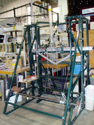
Experimental Chamber
Initially we worked with an experimental chamber with a visual working area 1-foot wide by 2-feet tall. Drawings can be found here. It was 2 pieces of 0.5-inch thick glass, sealed onto precisely machined side-rails by o-rings, using what was basically a big C-clamp. Side rails were 1-cm thick. Top and bottom manifolds were screwed onto the chamber by attaching to the side rail. The beauty of this design was that there was no area hidden from the camera. The manifolds connected to the sand at the glass interface or within the chamber. A complete design is found here. The lower manifold provided hydraulic connection to the sand using porous metal plates. This allowed us to create a relatively uniform wetting front during water floods and maintain suction on the sand during drainage. We were thus able to bring the sand pack to a specific suction when looking at hysteretic effects. The top manifold was simpler, with multiple holes connecting to drain tubing.
Later experiments were performed in a 26×26-inch chamber with 0.75-inch thick glass walls. We performed all our remediation experiments in this chamber, including the dissolution of capillary trapped TCE using several surfactants and the chemical transformation of TCE using potassium permanganate. This chamber had its own problems because of its size and weight. The chamber, filled with sand and with both aluminum manifolds attached, required two people to lift which required handles and a design to distribute force away from the handles. The first time we rotated the chamber without the well designed handles we cracked the edges of the ¾ -inch glass. We also built a rotating, wheeled stand to move the chamber from the automated sand filler to the light box. A portable crane was used to lift the chamber onto the light box.
Sealing the top and bottom manifolds to the chambers was more of a challenge than the side rails because we needed to be able to remove the manifolds if something went wrong during an experiment. In the early years we used a closed cell insulating foam to provide the seal but it tended to be too flexible and thus leaked under pressure. Both sides were glued to the chamber which required rebuilding the seal every time the chamber was opened. Plus you had to clean the old silicon glue off the chamber and manifold every time you replaced the seal. It was a good thing we had student interns to do this work! During one such cleaning a student came up with a better idea. Why not glue one piece of silicone gasket material to each side of the seal, one to the chamber and one to the manifold, and then use the gasket’s “self sticking” quality to create the seal? It worked like a charm. Cleaning the gasket with isopropyl alcohol prior to sticking it together creates a strong seal which has to be broken with a knife. The glued side rarely leaked. Once we began experiments using real DNAPLs (trichloroethene or TCE), we found the limitation of the silicone seal. The TCE would leak through the silicone seal mainly by volatilization. Silicone was replaced with Viton gasket material.
An additional challenge was presented with the 26-inch wide chamber. Though the manifolds were1.5 to 2-inch thick aluminum, there was still some deflection, or bending, at the ends of the manifold when we bolted them on to the chamber. With the ends slightly bent the manifold was not pushed against the seal with adequate force and a slow leak formed in the center. The lower manifold took care of itself because the weight of the glass plates helped to complete the lower seal. To finish the upper seal we had to add an automobile spring, bolted down at each end to add force to the center of the manifold. By increasing the force on the spring we could adjust the bend of the top manifold until it sealed.
Experimental Fluids
Initial experiments were performed using Soltrol-130 (Soltrol), a non-carcinogenic, lighter than water, oil analog for a DNAPL. The chamber was inverted and the Soltrol-130 was injected from the bottom via a port drilled though the front glass. A drill press designed for rock coring was used to drill the hole and the septum was created from silicon glue. The septum could be used for several experiments before it began to ooze water and needed replacement. We performed three experiments using Solotrol-130 percolating upward in order to view the flow paths through the designed sand pack and to shake any bugs out of the data collection system. Then we performed experiments with trichloroethylene (TCE) which was a common industrial degreaser and a relatively common contaminant in aquifers. Repeatability of experiments with oils was impossible as any remediation of the system changed the wetability of the sand thus changing the system’s initial conditions. This led us to two different methods of repeating experiments, using a gas which could be dissolved in water (CO2) as a NAPL analog and developing a technique to build sand packs in a repeatable manner.
CO2 was used as a NAPL analog because it could be easily removed from the chamber by dissolving with deaired water. In the experiments we started with a water saturated chamber and then flooded three pore volumes of CO2 saturated water through the chamber to displace the original water. Next we injected CO2 into the chamber at varying rates to simulate an incompressible NAPL. After the experiment the CO2 was easily dissolved with deaired water leaving the system essentially unchanged. This technique allowed for running one or two experiments per day with no change in the sand pack. It also brought out behavior in the NAPL – sand pack system (i.e. “throbbing”) which was faster and more obvious with a compressible gas than it was with an incompressible liquid.
Liquid characteristics were determined experimentally because we modified the NAPLs by adding Oil Red O dye for visualization purposes. Water was sometimes dyed with FD&C blue #2 and in Soltrol experiments we added salt to water in order to increase the difference in density between the aqueous phase and the NAPL. Viscosity was measured using Cannon-Fenske viscometers. Interfacial tensions were measured using the duNuoy Ring Method and density was measured using capillary pycnometers.
Experimental Sand
An automated sand filler was designed and built in order to fill experimental chambers with sand in repeatable heterogeneous patterns. A computer controlled robot arm provided static or dynamic positioning of a sand hopper above the chamber. Sand fell from the hopper into a funnel and down a tube to a precise location within the chamber. In the static case a measured portion of sand (Accusand) was poured into the funnel which created a mound at the bottom. By varying the size, amount, and location of the emplacement we filled the chamber with sand creating a designed flow path for the NAPL. In the mounded, heterogeneous sand packs, the original pattern had little geologic significance. But if it was turned upside down it resembled a vertically exaggerated “scour-and-fill” river deposition pattern. So we filled our chambers upside down.
In dynamic positioning we controlled the speed and direction of the hopper and the flow rate of the sand. As the hopper moved across, sand fell into the chamber creating graded layers. The sand, originally packed in a homogeneous manner in the hopper was graded as it fell, in a manner similar to Stoke’s law, such that the coarser grains deposited first, followed by the finer. Thus we created uniformly layered sand packs. The finer sand formed capillary barriers between the coarser layers which then controlled flow patterns of the NAPL in saturated conditions.
Experimental Procedures
Chambers were filled with sand using the automated sand filler, if we wanted a heterogeneous pack, or with Bob Glass’ Homogeneous Filling Techniques(Patent Pending)
if we wanted a homogeneous pack.
CO2 was delivered to the chamber at atmospheric pressure. Our supply tank was connected at a low flow rate to a container connected to the supply needle yet open to the atmosphere With this connected to the chamber we would then apply a suction to the top of the chamber using a syringe pump. As water was pulled out of the top of the chamber we opened the chamber to the CO2 at the bottom. The syringe pump allowed for uniform flow rates and a relatively good measure of volume displaced in the chamber. We ran experiments at flow rates of 0.1, 0.3 1, 2, 3, 5, 8, 10 and sometimes 15 ml/min depending on the sand pack. High flow rates through well graded sand could lead to piston-like displacements of the water. A digital flow meter designed for delivering hydrogen to gas chromatographs was used also to monitor flow rates. We collected video footage of the output but never analyzed it. Early experiments simply tried to inject CO2 into the chamber but they suffered from very inconsistent flow rates with large pressure fluctuations in the delivery line.
Delivering NAPLs to the chamber was much easier in comparison. The NAPL was loaded into a digital syringe pump and injected into the chamber. The outflow from the chamber was collected on an electronic scale and recorded on a computer as a check on the programmed flow rate. Delivering any non-wetting liquid from a needle into a water wet system will generate capillary pressure fluctuations at the needle tip. To monitor this we installed a pressure transducer able to read millimeters of water just prior to the needle on the NAPL delivery line. The output from this transducer was collected using a data acquisition program, LabTech Notebook.